19
2022.04
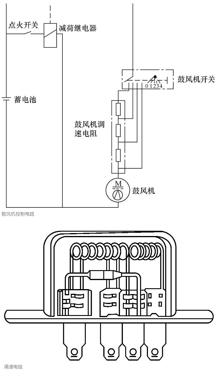
The control method of switch and speed regulating resistance consists of two parts: blower switch and speed regulating resistance. The speed regulating resistance is generally installed on the air conditioner evaporator component and uses air flow for cooling. The blower switch is generally installed in the control panel, and different gears are set for For speed regulation. When set, the blower switch can control both the positive pole of the power supply and the grounding circuit of the blower. Adjusting the blower switch can change the access mode of the speed regulating resistor, that is, change the current in the blower circuit to adjust the blower speed. The control gears of the blower are generally 2, 3, 4, and 5 speeds, and the most commonly used is 4 speeds.
When the blower switch is at 1, three resistors are connected in series in the blower circuit, and the fan runs at low speed; when the blower switch is at 2, two resistors are connected in series in the blower circuit, and the blower runs at low speed; when the blower switch is at 3, the blower circuit A resistor is connected in series, and the blower runs at high speed; when the blower switch is at 4, no resistance is inserted in the blower circuit, and the blower runs at the highest speed.

